These 4 options are available for the RS-3000
Option #1
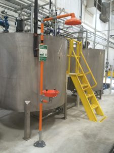
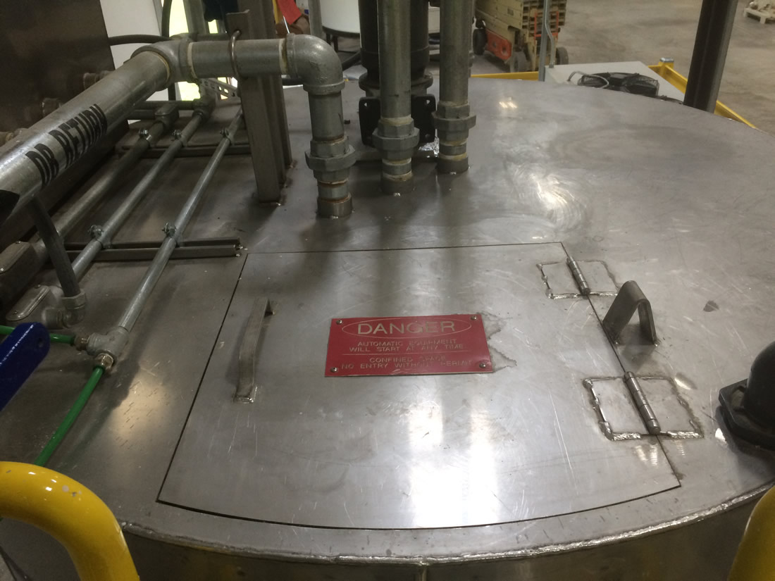
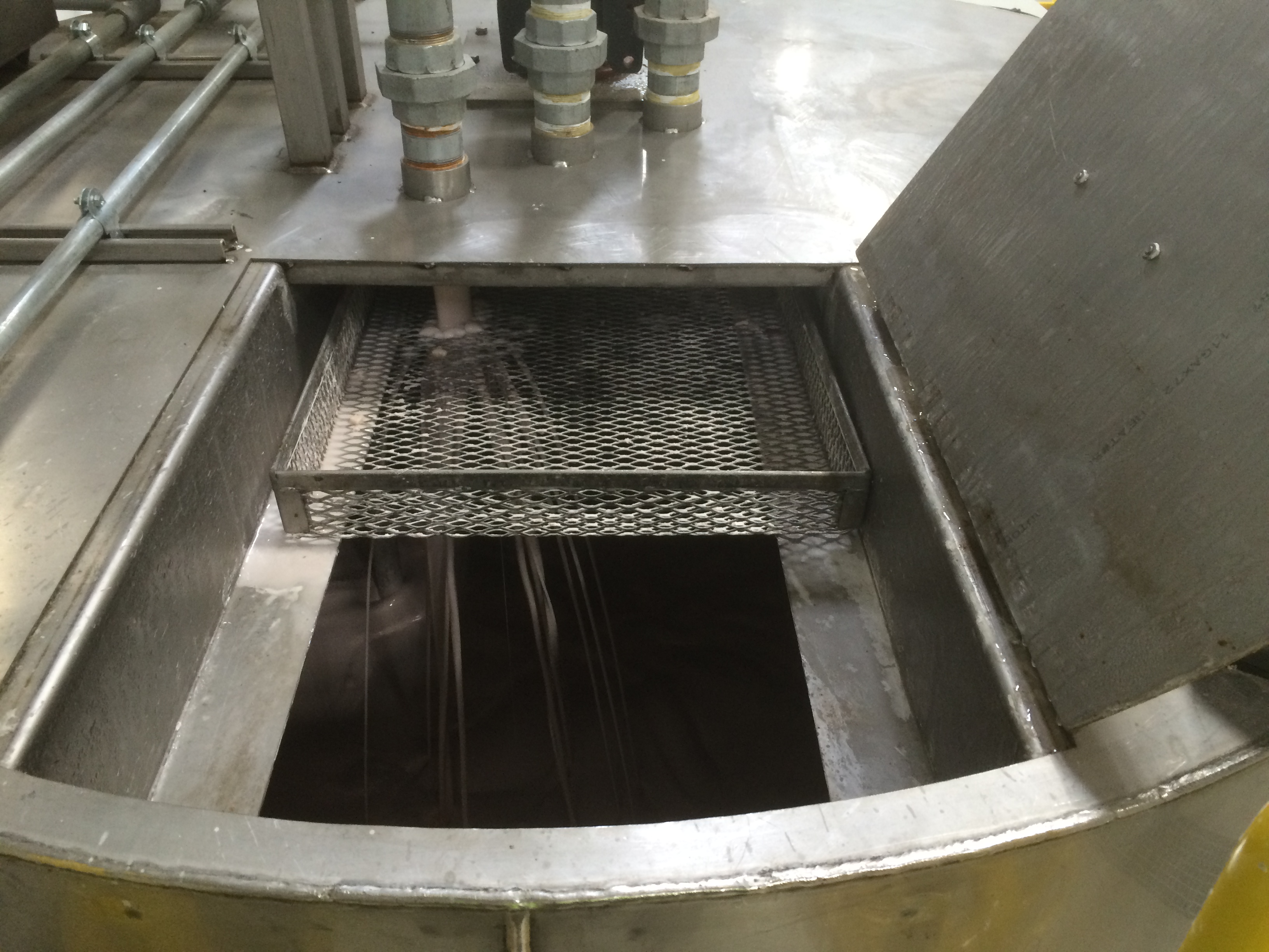
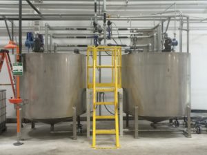
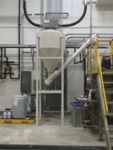
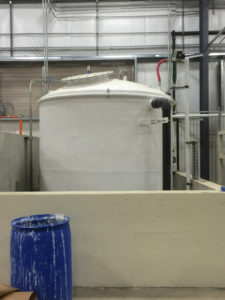
TWO 1,000-GALLON STAINLESS STEEL STORAGE TANKS
(2) 1,000-gallon dished bottom storage tanks constructed of stainless steel. Each tank includes required inlet / outlet fittings, hinged access door, strainer basket, and gasketed clean-out hatch / man-way in the side wall. Note: Each tank will be constructed of stainless steel for all wetted components. All non wetted parts are constructed of H.R.M.S. and painted with an epoxy-based paint. (View Image 1 & View Image 2 & View Image 3)
- Agitators (for confined entry)
(2) Vertical agitators, featuring 2 HP, C-face motors, 1” diameter shafts, and 10” solid bore propeller. View Image - TVC System
- (1) Rectangular TVC tank constructed of stainless steel with cover to aid in heat retention and minimize water loss through evaporation.
- (2) 12 KW immersion heaters to heat water in the TVC tank.
- (1) R.F. level probe and ½” solenoid to maintain water level in TVC tank, and to protect heaters in the event the water supply is shut down.
- (2) Circulation pumps to circulate heated water from the TVC tank through the coils to heat the adhesive in each storage tank.
- (3) Temperature probes and controls to maintain a desired temperature of stored adhesive and to control the TVC tank temperature.
- (1) Set of additional electrical controls to be located in the main starch system control panel. The TVC automatic mode features operation of storage tank agitators when the TVC hot water circulators are running. Override time guarantees agitation five minutes every hour, for example, during summer months when temperature input is not required.
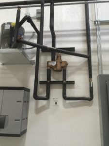
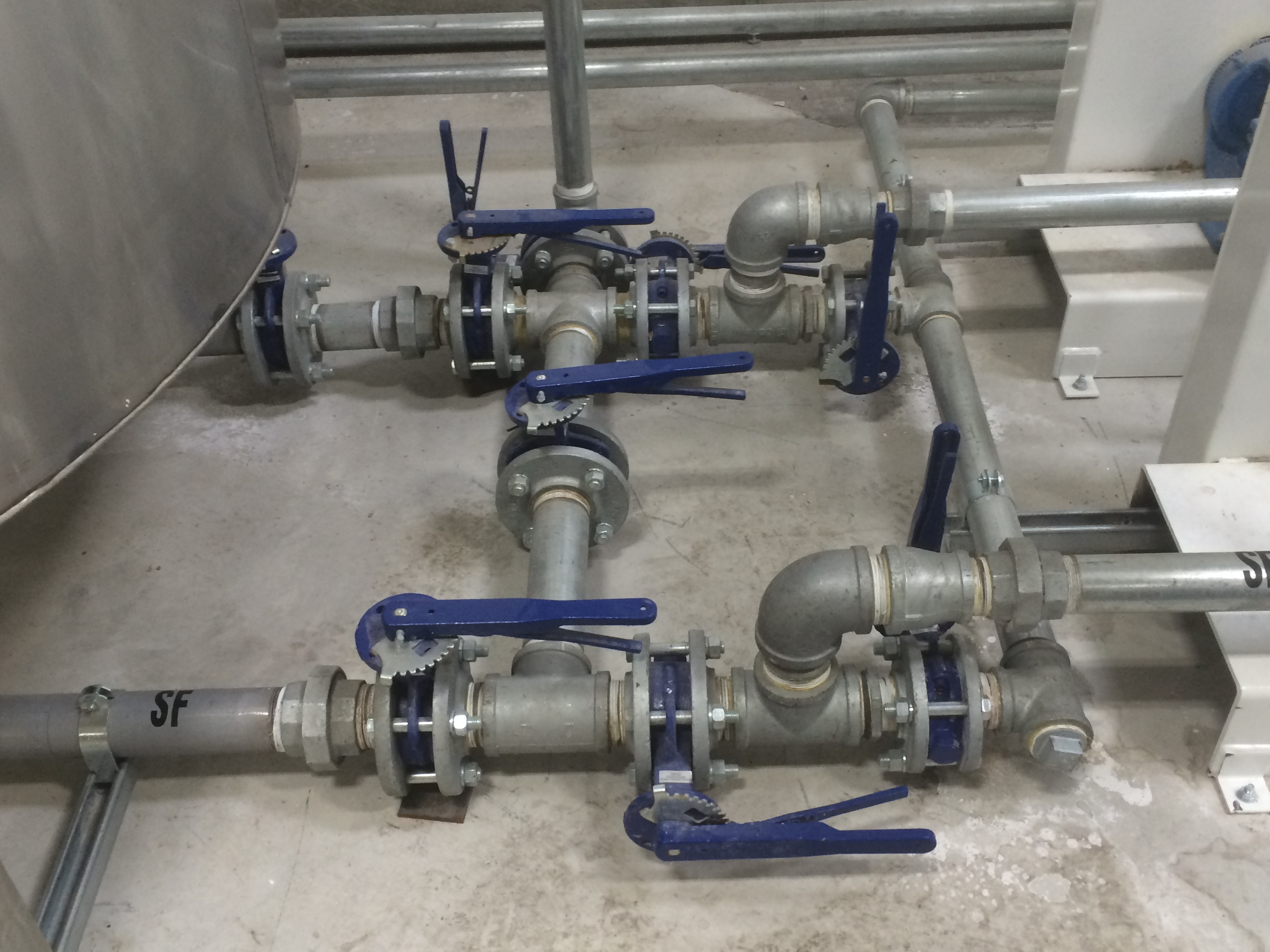
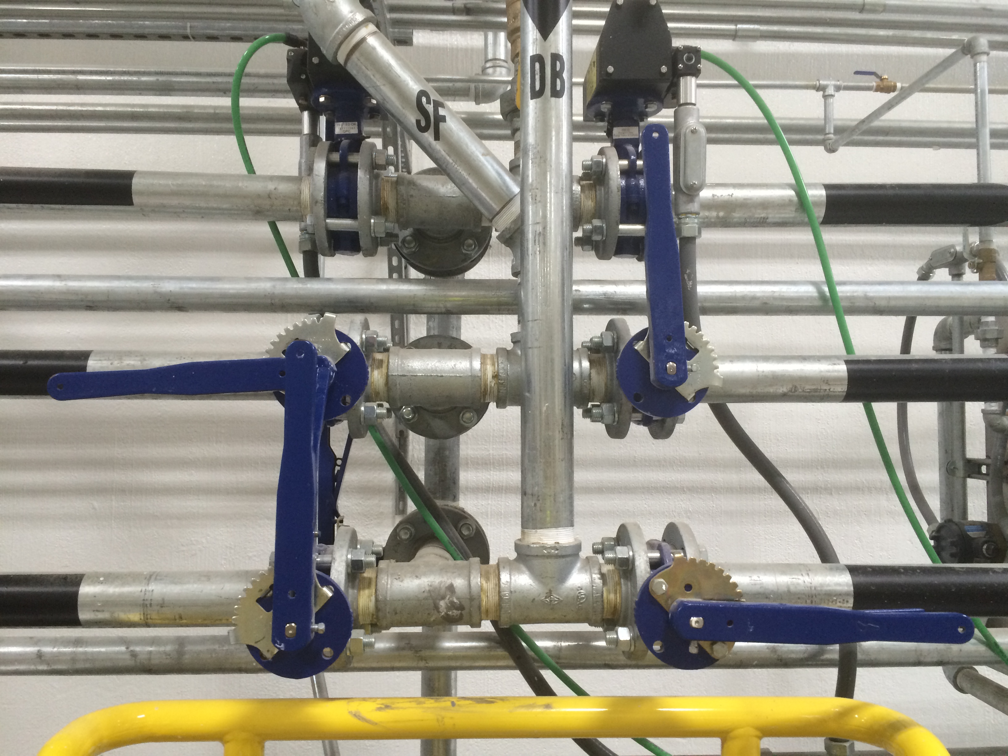
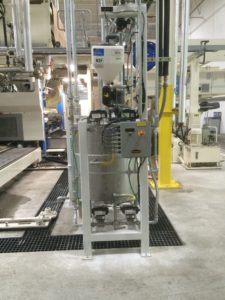
- Manifolds
(1) Lot adhesive manifolds constructed of 2” SCH 40 pipe with required fittings and 2” butterfly valves with position locking handles. The following are included:
- Suction (storage tank to pumps) – View Image
- Discharge (pumps to loops) – View Image
- Return (loops to storage tanks) – View Image
- Transfer (finished adhesive to storage tanks) – View Image
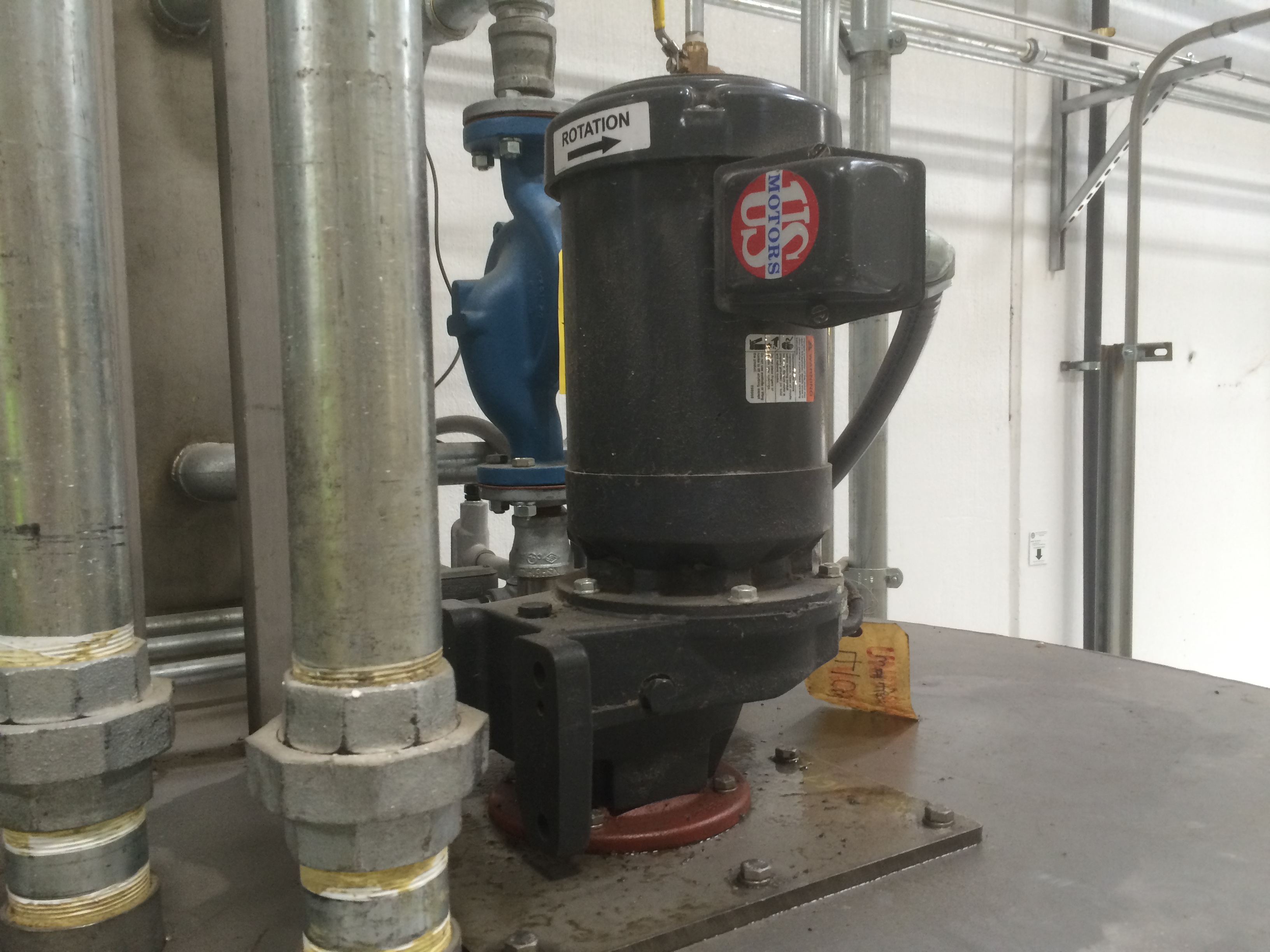
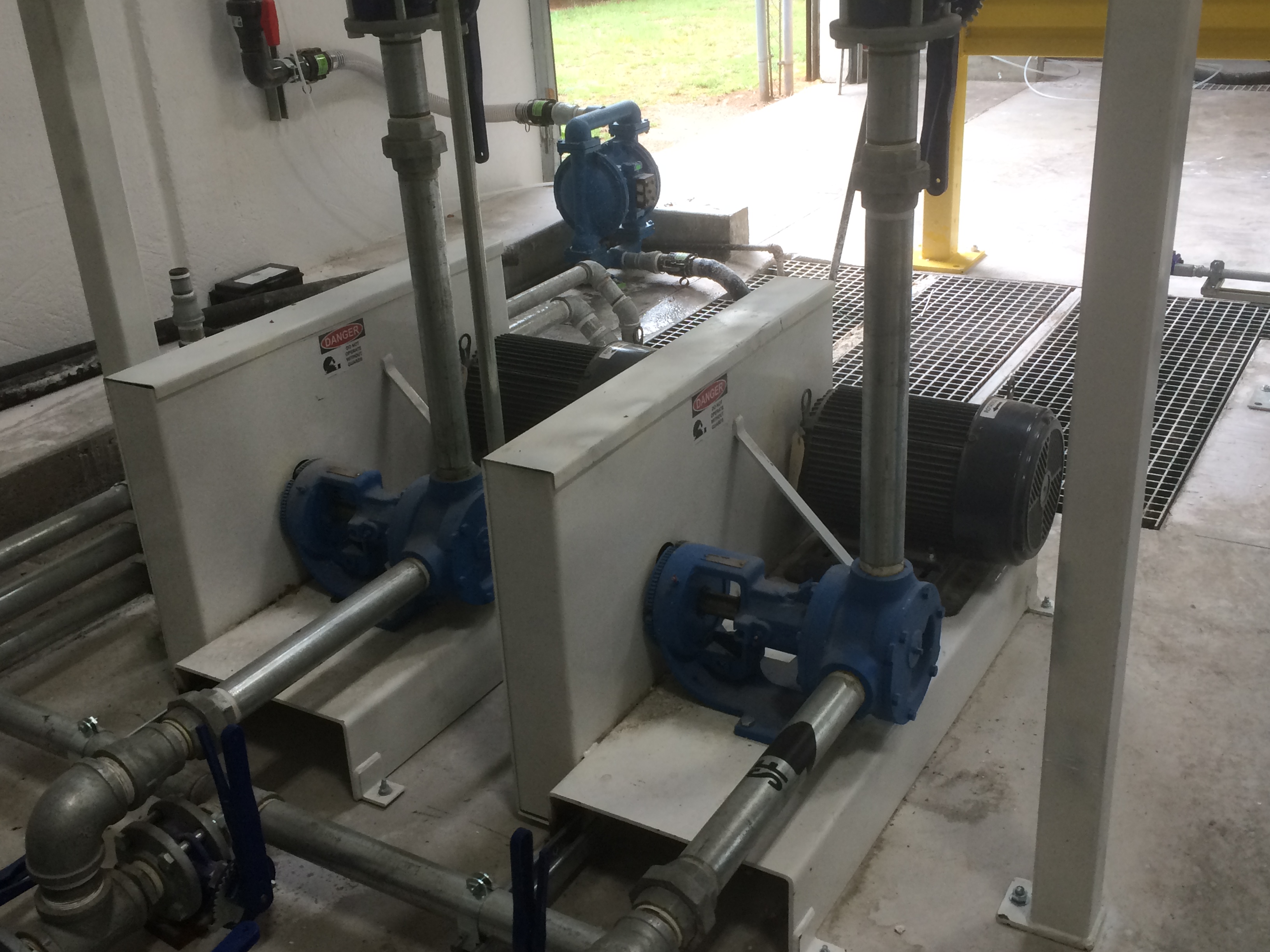
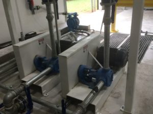
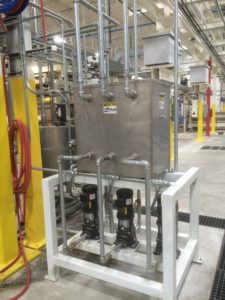
- Supply Pumps
(2) Heavy-duty 2” Viking pumps and motor sets. Each pump motor set includes a T.E.F.C motor, sheaves, belts, guard and floor mounting base. Each pump will circulate adhesive from the starch room to the new or existing corrugator loop piping – View Image

Option #2
BULK STARCH SILO
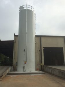 131,000 LB. CAPACITY BULK STARCH SILO (12’ X 42’) (3.28)
This item consists of a silo, dust collector, cone aeration, and other equipment to store pearl starch. It includes:
- (1) Heavy-duty 12’ diameter x 42’ eave height silo to store approximately 131,000 lbs. of starch weighing 40 lbs. per cubic foot. The silo is fully skirted with welded construction and has the following features:
- (1) Access ladder with fallback and landing to meet OSHA requirements
- (1) Top railing with toe board.
- (1) Exterior surfaces painted with white enamel
- (1) Interior surfaces lined with non-FDA epoxy.
- (1) Explosion relief deck (weak seam design).
- (1) Bolted cone access man-way
- (1) Skirt access door.
- (1) 60º cone design.
- (1) Pressure vacuum relief valve.
- (1) Top access man-way.
- (1) High level (overfill) probe with audible alarm.
- (1) Low level probe with indication and alarm at starch room.
- (1) Truck fill station, complete with required fittings, 4” O.D. aluminum tubing, elbows and couplings.
- (1) Silo grounding package with clamp to ground delivery truck during the unloading process.
- (16) Aeration pads with manifold, pressure reducer, and control valve to aerate the silo using the plant’s compressed air.
- (1) Bin vent with nine pleated filter cartridges (202.5 sq. ft. breathing area), solid-state timer, and solenoids. This bin vent uses reverse blow down for cleaning.
- AUGER (SILO TO MIXER)
This item is used with the new or existing silo to feed pearl starch to the mixer; it includes:
- (1) Lot required transitions.
- (1) 6” O.D. auger housed in 7” O.D. mechanical tubing. The motor is rated “inverter duty”.
- (1) V.F.D. to control auger speed and thus accuracy.
- (1) Pair 6” butterfly valves, each with double-acting pneumatic actuator.
- (1) Set of additional electrical controls housed in the control panel listed earlier.
 150’ PNEUMATIC BULK STARCH CONVEYING SYSTEM
Two-way, closed loop system designed to convey starch up to 150’ from the silo to the included 1,500 lb. capacity receiving hopper and auger (with V.F.D.) delivery system. It includes:- (1) Conveying blower equipped with a T.E.F.C. 1,800 RPM motor mounted on a common base with guards, pulleys, belts, and a positive displacement blower.
- (1) Rotary airlock, slidegate, and transitions to meter starch into the conveying line.
- (1) Lot (approximately 350’) of aluminum tubing with 36” radius long sweep bends.
- (1) Lot required 3-bolt compression couplings with ground strip.
- (1) Lot (approximately 30’) of material handling hose with hose shanks and hose clamps as required.
- (1) Set of electrical controls (to be located at the silo skirt) in a dust-tight cabinet. These controls are to be pre-wired to terminal strips, consisting of side operated disconnect, control circuit transformer, selector switches with indicating lights, and starter with line and overload protection for the blowers, rotary airlock, and all other equipment located at the silo.
- (1) 1,500 lb. receiving hopper equipped with one vibrator and one airpad to eliminate hopper bridging, etc.
- (1) Hopper level probe for fill control.
- (1) 6” O.D. auger housed in a 7” O.D. mechanical tubing to feed pearl starch to the mixer. The auger is V.F.D. controlled.
- (1) Pair 6” butterfly valves, each with pneumatic actuator to seal the wet mixing process from the dry bulk starch.
- (1) Set of additional electrical controls to be housed in the starch room control panel.
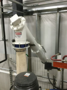
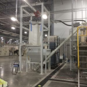 SUPER SACK HOPPER (FOR MODIFIED CARRIER STARCH)This item is intended to add dry modified starches in those plants that choose to run a modified carrier. It includes:
- (1) Steel hopper designed to hold pearl starch (approximately 1,500 lbs.). This hopper has been designed for use with a customer supplied crane (jib or gantry) and hoist. It is equipped with a turbine vibrator to prevent bridging.
- (1) Lot required transitions
- (1) Rigid auger with fixed drive
- (1) Pair 6” butterfly valves, each with double-acting pneumatic actuator
- (1) Set of additional electrical controls housed in the control panel listed earlier in this proposal
Option #3
CORRUGATOR DELIVERY NETWORK
- Dual Viscosity Loop
We propose to provide all pipe, valves, and fittings for a standard two-viscosity corrugator loop around the corrugator. Construction is to be 2” sch. 40 galvanized pipe with standard 150# galvanized fittings (no long sweep elbows) and bronze ball valves. The loop is to be no more than 50 ft. from the starch storage tanks and no more than 275 ft. in total length one-way (starch room to farthest glue pan). This loop will have one leg dedicated to the single facers and another loop dedicated to the glue machine.Note: Loop insulation is not included. - Three (3) Corrugator use Tanks System
 The corrugator Use Tanks work in conjunction with a corrugator loop to feed adhesive to both single facers and the glue machine. This allows better adhesive flow control, necessary with some modern corrugators. In addition, resin dosing, heating & cooling (optional) are available. The Use Tanks are refilled automatically from the loop. This system includes:
- (3) 100 gallon cone-bottom tanks fabricated from 304 stainless steel.
- (3) 1 hp agitators with stainless steel shafts and propellers.
- (3) Sets of dual 1 ½” air diaphragm pumps to transfer adhesive to the corrugator and return it to the Use Tanks. Pumps are also used to return adhesive to storage when necessary.
- Level probes.
- Actuated butterfly supply valves.
- Lot manual ball valves and piping manifolds to allow full adhesive transfer options.
- NEMA 4 control panel to house the required electrical controls. A PLC controls the system, and an Operator Interface displays equipment status and provides a means to change settings. The Use Tank system is also accessible from the optional mix system Remote Computer.
- Weighed Resin Addition to use Tanks
This item includes the equipment required to turn each of the three Use Tanks into a resin doser. It includes:- Weigh tanks and scales for precise addition
- Resin addition pump
- Control valves
- Additional electrical controls to be housed in the Use Tank control panel listed previously.
 Heating for Three Use Tanks
This item provides hot water heating, circulation pumps, and controls for heating the Use Tanks. Included:- Rectangular hot water tank constructed of stainless steel with cover to aid in heat retention and minimize water loss through evaporation.
- (3) Circulation pumps to circulate heated water from the water tank through the Use Tank jackets to heat the adhesive in each Use Tank.
- Lot – Temperature probes and controls added to the Use Tank system control panel to maintain temperatures in the hot water tank and Use Tanks. The use tank agitators run when the hot water pumps are running.
Option #4
1,000 GALLON DOUBLE-WALL FIBERGLASS BULK CAUSTIC TANK
 This item includes a Double-Wall Fiberglass Bulk Caustic Tank with temperature control and leak detection. It includes:
- Flat bottomed, domed top, with 5’0” inside diameter and 7’6” straight shell height, 9’0” overall height, 1,091 gallons capacity.
- Bottom and top reinforcing flanges.
- Fiberglass reinforced double-walled construction, manufactured in accordance with specification NBS PS15-69
- Inner corrosion liner fabricated with premium vinylester resin, reinforced with 10 – 20 mil “C” glass surface veil, and backed with 100 mil chop strand fiberglass laminate. Balance of laminate fabricated to full wall thickness with premium vinylester resin
- 2” polyurethane foam insulation for sidewall and dished top
- Exterior surface finished with white protective coating with ultraviolet inhibitors
- Bottom anchoring flange, reinforced with gussets.
- Heating system to maintain 100° F at minimum ambient temperature of 55° F. It allows constant display of the tank temperature at the existing starch system and sounds an alarm if the caustic temperature is out of range. The temperature alarm is displayed at the existing starch system and recorded in the alarm history.
- Overfill probe to signal an overfill situation. The probe is hard-wired to an alarm horn at the fill site and closes the automatic shut-off valve. The overfill alarm is displayed at the existing starch system and recorded in the alarm history.
- Ultrasonic Level Transmitter provides an adjustable “fill to” signal that alerts the filling personnel that the tank is full. It allows constant display of the tank level at the existing starch system. It also provides an adjustable low level reorder notification.
- A leak detector signals that the inner wall has failed and caustic has leaked into the cavity between the tank walls. The leakage alarm is displayed at the existing starch system and recorded in the alarm history.
- Stainless steel coupler, locking handle ball valve, alarm horn, and warning signs to be located at the fill site.
- 4” vent / overfill pipe
- 24” flanged and bolted top manway.
- Safety Shower/Eyewash Stations
Includes safety station with eyewash and shower with tepid water mixing valve- 3 Eyewash/Shower Safety Station (mixer deck, floor near mixer, floor near bulk caustic tank) – View Image
- 3 Tepid Water Mixing Valve – View Image
- Customer to provide and connect hot and cold water to each of the stations (total three locations).
- Customer to provide any privacy curtains desired.